|
Specifications for
the Baltimore & Ohio RR Locomotives 199 & 204 |
| |
| Confederate Names: #199 -- Dixie; #204 -- Unknown |
| |
| Information found in Bell, The Early Motive Power of the
Mobile & Ohio Railroad, 1912, pages 88-92, reformatted for
ease of reading. |
| |
| #199 was built in November, 1853, and #204 in March, 1854,
both by A. W. Denmead & Sons. |
| |
| Cylinders: 19" x 20" |
| Driving Wheels: 50" |
| Truck Wheels: 28" |
| Weight: 60,000 pounds |
| Boiler shell: 5/16" iron, in straight form |
| Boiler diameter: 48" |
| Number of tubes: 160 |
| Diameter of tubes: 2 1/2" |
| Length of tubes: 14 feet 4" |
| Firebox: 42" x 58" |
| |
| Scroll down for a complete, detailed
description. |
| |
|
|
| |
| The following article appeared in an article by
M. N. Forney, in the American Engineer and Railroad Journal,
was prepared by W. S. G. Baker, and on account of its
completeness and accuracy, is thought to be of sufficient
interest to be hear repeated: |
| The cylinders were 19 x 20 inches, with spring
packing and brass rings on the pistons, the piston rods being of
iron, 2 3/4 inches diameter. The steam ports were 1 1/2 by 14
inches, the exhaust port 2 1/2 by 14 inches, the travel of the
valve 4 1/2 inches. The crossheads were made of brass, with
gun-metal gibs at the top and bottom, arranged with bolt and
wedge-shaped tops to take up wear. The guide rods were of
wrought iron, and of diamond section. The main rods led to the
centre driving-wheels and were 7 feet 7 inches from centre to
centre. The tires for the main and leading drivers were 6 1/2
inches wide and blind, the rear drivers having flanges. The
centres of all the drivers were of cast iron, fitted with
chilled-faced cast-iron tires, put on with a taper fit and held
by lateral hook keys and nuts. |
| The driving-wheels were 50 inches diameter and
52 inches centre to centre. The truck-wheels were 28 inches in
diameter, with chilled faced, placed 36 inches, centre to
centre, and the centre of the truck was 15 feet 8 inches from
the centre of the rear driving-wheels. The main axle was 5 1/2
inches in diameter, the others being 5 inches. The total weight
of the engine was 60,000 pounds, about 48,000 pounds being on
the drivers. |
| The truck bolster was of wrought iron, with its
centre forged on, the journals formed at the ends and fitted
into housings resting upon and keyed to semi-elliptic springs,
36 inches long, the ends of which rested and slid within seats
formed on top of the truck frames. The frames were of wrought
iron, with the pedestal jaws forged on. The jaws were slotted to
shape and fitted with cast-iron shoes and wedges adjustable from
below. The axle boxes were of gun metal and the springs were
semi-elliptic, graduated. They were equalized upon the main
boxes and were connected to the boxes by pins passing through
the frames upon which the springs rested. The frames were
rigidly secured to the smoke-box but were free at the firebox
end and so arranged that the boiler was free to slide upon them
and was held in place by sleeves passing around the frames and
bolted to the firebox. |
| The boiler was horizontal and straight. It was
48 inches in diameter, with single rivetted seams, and was made
of 5/16-inch iron. The dome was 30 inches diameter and 36 inches
high, with a cast-iron flange and top made with a ground joint.
The safety valves were formed in the top and connected by a
lever to a spring balance. The dome was placed 54 inches back of
the front flue sheet. The firebox was of copper, with 5/16-inch
sides and 5/8-inch flue sheet. It was 42 by 58 inches in size
and there were 160 2 1/4-inch flues of lap-welded iron 14 feet 4
inches long. |
| The feed-water was supplied by two
single-action pumps attached to the sides of the firebox and
operated by cranks attached to the crank pins of the rear
driving-wheels. The feed-water entered the boiler by checks
immediately in front of the back flue sheet, and was then
conveyed by a pipe inside the boiler and discharged immediately
back of the front flue sheet. Rocking grates were used, operated
by a lever on the foot-board, with a drop-grate in front. The
drawbar was attached to the ashpan as in the Winans camel
engines. |
| The valve gear was of the hook type, with
cut-off worked at half stroke, and operated by a separate
eccentric and rocker. The vale stem of the cut-off was so
arranged that it could be thrown out of gear, the valve
remaining stationary when the cut-off was not used. |
| Steam was taken from the top of the dome
through a slide-valve throttle, operated by a crank connected to
a screw with large pitch. The gage cocks were in the waist of
the boiler below the foot-board of the cab and operated by long
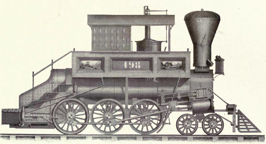
stems and levers. The pilot in front of the engine was so
arranged that it could be folded back when not on the road. This
was done to permit of closing the doors of the engine house when
the engine was in the stall. The smoke stack was arranged for
soft coal fuel. It was formed with a centre pipe 12 inches in
diameter, over which a cast-iron deflector was placed. This was
to deflect sparks into a hopper formed by a second pipe, with a
space between it and the central one. This space was provided
with an outlet at the bottom to facilitate the removal of
accumulated sparks. The top was provided with a bonnet hinged to
the stack and covered with iron netting. |
|